En este campo, se plantea frecuentemente la recuperación de un forjado formado por viguetas de madera y un entrevigado con soluciones constructivas muy diversas, dependiendo de la época y lugar de construcción; en ocasiones, esta situación responde a motivos puramente económicos, mientras que otras veces se hace por el valor histórico-artístico del edificio, que justifica este refuerzo aunque sea más costoso que la sustitución. Las causas que generalmente obligan a adoptar este tipo de medidas son:
- La degradación de la madera, que se traduce en una disminución de su sección resistente
- El cambio de utilización del edificio, que equivale normalmente a un incremento de las cargas de servicio
- Motivos funcionales, tales como deformaciones, vibraciones, etc.
- Otras razones diversas, para adaptarse a normativas recientes (protección contra incendios, insonorización, etc.) que quedan fuera del ámbito estructural en que se plantea este trabajo
Además de estas causas, consecuencia directa de una degradación o cambio de uso de la estructura, las crecientes exigencias en materia de seguridad hacen que estos forjados deban realizar también funciones que no se consideraban prioritarias en su época de construcción, tales como:
- Capacidad para funcionar como diafragma rígido en su plano, solidarizando todos los elementos verticales enlazados a él, de manera que tengan un comportamiento de caja que permita absorber las acciones horizontales
- Capacidad para redistribuir las cargas gravitatorias entre los distintos elementos lineales que lo componen, de forma que si alguno de ellos resulta sobrecargado pueda trabajar conjuntamente con los adyacentes
Además de los problemas de flechas citados en el párrafo anterior, a los que no se ha prestado suficiente atención hasta época relativamente reciente.
Una solución que tradicionalmente se ha venido aplicando, y que en ocasiones constituye una mala práctica constructiva, es la colocación de una solera de hormigón ligeramente armado sobre el forjado existente previamente saneado, sin ningún tipo de conexión entre ambos. Esto hace que las dos partes del forjado así constituido trabajen independientemente, con lo que el incremento de la capacidad portante y de la rigidez del conjunto es escaso; la única ventaja de este procedimiento es que permite la redistribución de cargas entre las viguetas, teniendo como inconveniente el incremento del peso propio que puede llegar a compensar, e incluso superar, la eficacia del refuerzo que se consigue.
El estudio realizado, corresponde al comportamiento de esta misma solera de hormigón como refuerzo del forjado, cuando se disponen adecuadamente elementos de conexión con la vigueta para que el conjunto trabaje solidariamente como una pieza mixta de hormigón y madera. El objetivo es lograr que el hormigón, o la mayor parte de él, trabaje a compresión, con lo que se consigue aumentar el canto resistente del forjado, y el de todas las características mecánicas que condicionan su comportamiento a flexión; para ello, es preciso que los conectadores sean capaces de absorber los esfuerzos rasantes que se generan en la superficie de contacto entre ambos materiales.
Tal como está planteado el problema hasta aquí, se limita al análisis de una pieza mixta similar a las que con frecuencia se proyectan de hormigón y acero, pero con algunas variaciones como consecuencia de la tipología específica que vamos a considerar:
- Los conectadores. Estos elementos, generalmente metálicos, producen el aplastamiento de la madera al transmitir los esfuerzos rasantes, lo que equivale a un deslizamiento relativo entre hormigón y madera, que influye sensiblemente en la distribución de esfuerzos.
- El espesor de la solera de hormigón. Para no incrementar excesivamente el peso propio del forjado, que condicionaría negativamente el campo de aplicación de esta solución, tenemos que ir a espesores de hormigón pequeños, que no permiten la colocación de armaduras longitudinales y transversales en la posición que sería deseable.
- La vigueta de madera. Por tratarse de un estudio de rehabilitación en el que la madera es un material existente, sus características las hemos de determinar a partir de ensayos; teniendo en cuenta la heterogeneidad propia de este material, más aun en construcciones antiguas a las que nos estamos refiriendo, y que la toma de muestras, la mayor parte de las veces, no puede hacerse ni en el número ni en la localización que sería deseable, este valor sólo lo podemos determinar con aproximación, lo que obliga a utilizar coeficientes de seguridad razonablemente conservadores.
- Los efectos reológicos. Este tipo de fenómenos, aunque de forma diferente, afectan tanto al hormigón como a la madera.
En este caso concreto, el hormigón es un material de nueva colocación que va a experimentar estos efectos, por lo que deben ser evaluados; pero la madera, tanto por su antigüedad como por el tiempo que ha estado cargada, ya ha experimentado todos sus movimientos diferidos, por lo que no los tendremos en cuenta, considerando que no se ve afectada por ellos.
A partir de este planteamiento general, el trabajo se inicia con una revisión del estado de la cuestión, recopilando y analizando tanto las soluciones constructivas que se han desarrollado para resolver este problema, como las tipologías de conectadores y procedimientos de cálculo teóricos y/o experimentales. De los procedimientos estudiados se desprende que, o bien abordan el problema desde una perspectiva parcial, o cuando lo enfocan con carácter general llegan a resultados excesivamente complejos que hacen inviable su aplicación práctica.
Con esta premisa se ha trazado el objetivo del trabajo: elaborar un procedimiento de cálculo que permita utilizar las soluciones constructivas usuales con sus variantes (cabeza de hormigón rectangular o en T, distintas tipologías de conectadores y calidades diversas de hormigón y madera), cuya aplicación práctica sea viable, a la vez que se puedan evidenciar claramente las relaciones que existen entre las distintas variables para facilitar las decisiones desde la fase inicial del proyecto.
Con este objetivo, se ha realizado inicialmente un análisis teórico del problema que incluye las variables representativas de las magnitudes y situaciones de proyecto que se pueden plantear; como era de esperar, los resultados obtenidos son complejos, tanto por la propia naturaleza del problema como por la cantidad de variables que intervienen.
Por ello, se ha desarrollado a continuación un programa de cálculo interactivo, que permite, fijando los valores de las magnitudes que consideramos como datos del problema, obtener los valores de las demás variables que definen el dimensionado completo del forjado, de manera que se verifiquen las condiciones de equilibrio y compatibilidad, a la vez que tenga en cuenta la influencia de los efectos reológicos con las premisas que se han indicado anteriormente.
Este programa resuelve el problema de cálculo, entendido en el sentido de que permite definir las dimensiones de una solución ya proyectada. Pero en las estructuras arquitectónicas, antes que este problema aparece otro: el diseño de una solución previa, con dimensiones razonablemente aproximadas, que sea viable tanto desde el punto de vista constructivo como económico; por lo que también se ha incluido esta perspectiva en el trabajo.
Para ello, utilizando las relaciones analíticas obtenidas y aplicando el programa desarrollado, se han elaborado unas gráficas que interrelacionan las distintas variables y permiten determinar con suficiente aproximación en los casos estudiados (que corresponden a los que habitualmente se suelen plantear) los valores de las variables consideradas como incógnitas.
Para esta última fase del problema, teniendo en cuenta que las representaciones gráficas que resultan como aplicación inmediata de los resultados teóricos, no corresponden a líneas sino que son nubes de puntos que delimitan la tendencia de la ley de variación, se han empleado criterios de regresión.
Como todo trabajo de investigación que se desarrolla en el campo analítico, es necesario verificar sus resultados comparándolos con otros experimentales; para ello se han seguido dos líneas: por un lado, se han comparado los resultados que se obtienen por el procedimiento propuesto, con otros de problemas similares publicados en la bibliografía sobre la materia, verificando que se obtiene una buena aproximación.
La otra línea de experimentación, se ha tratado que fuera de
elaboración propia, siendo consciente desde el principio de que por
limitación de medios el número de experiencias que se podrían realizar
sería insuficiente para que la muestra pudiera considerarse
representativa. Para ello, en dos proyectos, se han realizado pruebas de
carga para efectuar comparaciones; como se indica en el capítulo
correspondiente, el comportamiento real de la solución propuesta es
sensiblemente más rígido que lo que se desprende del estudio analítico
realizado.
A frequent situation in this type of work is the preservation of a floor structure composed of timber joists and a variety of types of infilling depending on the place and period. At times the reasons are purely financial, at others, the historic or aesthetic value of the building justifies reinforcing the floor even though replacing it would be cheaper. The usual reasons that make this type of solution necessary are:
- The timber has deteriorated, decreasing its cross-section area.
- A change in the buildings use, which usually brings an increase in the service loads
- Functional reasons such as deformation, vibration etc.
- Other assorted reasons such as adaptation to recent regulations (fire resistance, sound insulation etc.) which lie outside the scope of this structural study
As well as these reasons, which are the direct consequence of deterioration or change of use, the increasing demands of the safety regulations oblige these floor structures to perform functions that were not considered a priority at the date when they were built, such as:
- The ability to function as a rigid horizontal diaphragm that binds together all the vertical elements connected to it in such a way that it acts like a box, absorbing horizontal stresses.
- The ability to redistribute gravitation loads among the linear components of the floor so that if any of these is overloaded the adjoining ones can absorb part of the load.
as well as the deflection problems mentioned in the previous paragraph, to which not enough attention has been paid until relatively recently.
A solution which has traditionally been applied, but can at times constitute bad building practice, is to repair the existing floor structure and cover it with a lightly reinforced structural concrete topping, with no type of connection between the two. As a result, the two parts of the floor structure function independently and there is very little improvement in the loading strength or the rigidity of the whole. The only advantage of this procedure is that it redistributes the load over the joists, the drawback is that the increased weight can cancel out, or even outweigh, the reinforcement achieved by this method.
This study examines the behaviour of the same concrete reinforcement of the floor structure when ties are placed at appropriate intervals to connect the topping slab to the joists so that the whole works together as a concrete and timber composite construction. The object is to ensure that the concrete, or most of it, absorbs the compression, thus increasing the vertical resistance of the floor structure and all the mechanical properties involved in its resistance to bending. Consequently, the ties must be capable of absorbing the shear stresses that are generated at the contact surface of the two materials.
As described so far, the problem is limited to an analysis of a composite construction similar to the frequently designed concrete and steel type. However, there are certain variations as a result of the specific type of floor under study:
- The ties. These pieces, generally made of metal, compress the timber as they transmit the shear stresses, causing the equivalent of a relative slippage between the concrete and the timber which has important consequences for the stress distribution.
- The depth of the concrete topping. The depth of the slab must be restricted in order to avoid an excessive increase in the weight of the floor structure that would limit the use of this solution in the field of application in question. As a result, lengthwise and crosswise reinforcements cannot be placed in the positions that might otherwise be desirable.
- The timber joist. Since the timber is an existing material, the rehabilitation study must carry out tests to determine its properties. However, this material is in itself heterogeneous and still more so in the old buildings under consideration. Additionally, in most cases it is not feasible to take samples in either the desired number or the desired places. Consequently, its properties can only be determined approximately and it is therefore necessary to employ fairly conservative safety allowances.
- Rheological effects. The movement and deformation of matter affects both concrete and timber, although in different ways. Here the concrete is newly laid and will undergo these effects, which must consequently be assessed. The timber, however, is old. It has been under stress over time and, therefore, has already undergone all its long-term movements. Consequently it will not be taken it into account as it is considered that such movements will not affect it.
Taking this general analysis as a starting point, the next stage was to review the state of the question by collecting and analysing the building methods that have been developed to solve this problem and the types of ties and theoretical and/or experimental calculation methods. The procedures examined lead to the conclusion that either they approach the problem from a limited, partial perspective or, if they adopt a general approach, the excessive complexity of their results makes their practical application unviable.
Given these premises, it was decided that the objective was to work out a calculation method that would enable the usual construction solutions to be employed, including their variations (topping slab rectangular or T section, different types of ties, different qualities of concrete and timber), would be viable in its practical application and would show the relations between the different variables clearly to facilitate decision-taking from the very first stage of the project.
With this aim in mind, the first step was a theoretical analysis of the problem that included the variables for the quantifiable factors and project situations that might arise. As was to be expected, the results are complex, both because of the nature of the problem itself and because of the quantity of variables involved.
The next step was therefore to design an interactive calculation program. Once the figures for the quantifiable factors, the given data of the problem, have been entered, the program enables the figures for the other variables that define the dimensions of the floor structure to be determined and checked for balance and compatibility. It also takes into account the influence of the rheological effects, based on the premises outlined above.
This program solves the calculation problem in that it enables the dimensions of a solution that has already been projected to be defined. However, in architectural structures another problem has already arisen before this stage is reached: designing a provisional solution that will be viable both constructively and financially, with reasonably approximate dimensions. This aspect has therefore also been included in this work.
For this purpose, the analytical relations (formulae) were entered into the program to produce graphs which interrelate the different variables and enable the figures for the unknown quantity variables to be determined to a sufficiently approximate degree for the cases studied (those that most commonly present themselves).
Bearing in mind that the immediate application of the theoretical results produces graphs which are not composed of lines but of clusters of dots that show the variation law trend, regression criteria were employed for this last stage of the problem.
In any analytical research it is essential to check the results by comparing them with experimental results. This has been done in two ways: the first was to compare the results obtained by this procedure with those of similar problems in the published literature on the subject. The results are found to match quite closely.
It was decided that the other experimental line would be attempted personally, despite being aware from the first that the limited means available meant that the number of experiments that could be carried out would not be sufficient for them to be considered representative. As a result, loading tests on two projects were performed for comparison. As indicated in the relevant chapter, the real performance of the proposed solution is noticeably more rigid than that predicted by the analytical study.
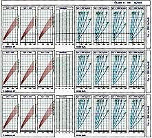
Aunque la forma de utilizar los ábacos puede ser muy diversa, vamos a exponer mediante un ejemplo, la manera directa y secuencial para obtener la carga total q en Kp/m. que agota la sección mixta según los criterios expuestos. Si suponemos una sección mixta con las siguientes características:
bxh = 12 x 24 cm. vigueta de madera
a = 70 cm. entrevigado
d = 5 cm. espesor del refuerzo de hormigón
L = 5 m. Luz de la vigueta
Si tomamos una tensión para la madera s w,adm. = 100 Kp/cm2 y hormigón de resistencia característica fck = 250Kp/cm2.
Como la relación H/B = 2 y el módulo resistente de la madera,
| w= | bxh2 | = | 12x242 | =1152cm3 |
| 6 | 6 |
si entramos en la tabla correspondiente a la calidad de madera y hormigón definidas (línea discontinua del segundo ábaco), trazaremos una línea vertical por el módulo resistente calculado hasta que intersecte con la curva correspondiente a d = 5cm., desplazándonos en horizontal hasta el gráfico de entrevigado, donde seguiremos las curvas allí marcadas hasta intersectar con la línea vertical que representa el entrevigado a = 70 cm.; a partir de este momento, el desplazamiento por el gráfico se realizará trazando una línea horizontal, que intersectará con las curvas correspondientes a L = 5 m. dentro de cada gráfico k/s, obteniendo los siguientes valores:
k/s = 500 Kp/cm2 · qtot = 600 Kp/m.
k/s = 750 Kp/cm2 · qtot = 650 Kp/m.
k/s = 1000 Kp/cm2 · qtot = 700 Kp/m.
k/s = 2000 Kp/cm2 · qtot = 730 Kp/m.
que comparados con resultados obtenidos del programa
k/s = 500 Kp/cm2 · qtot = 627 Kp/m.
k/s = 750 Kp/cm2 · qtot = 667 Kp/m.
k/s = 1000 Kp/cm2 · qtot = 694 Kp/m.
k/s = 2000 Kp/cm2 · qtot = 745 Kp/m.
vemos que son casi idénticos, ya que las diferencias en este caso vienen marcadas por la precisión que podemos obtener en los ábacos.
Although the abacuses may be used in many different ways, an example of a direct, sequential manner of obtaining the maximum load (qtot) in Kp/m for the composite section, according to the criteria explained above, is as follows:
Given a composite section with the following characteristics:
bxh = 12 x 24 cm. timber joist
a = 70 cm. infilling between joists
d = 5 cm. depth of concrete reinforcement
L = 5 m. Joist span
and taking the tensile strength of the timber as s w,adm. = 100 Kp/cm2 and a typical concrete strength of fck = 250Kp/cm2,
since the H:B ratio = 2 and the moment of resistance of the timber is
| w= | bxh2 | = | 12x242 | =1152cm3 |
| 6 | 6 |
go to the table for the timber and concrete properties in question (broken line on the second abacus), draw a vertical line through the moment of resistance you have calculated until it intersects the curve for d= 5 cm, then move horizontally to the infilling graph and follow the curves until they intersect with the vertical line that shows infilling a = 70 cm. Drawing a horizontal line from this point to intersect the curved lines for L = 5 m in each k/s graph gives the following results:
k/s = 500 Kp/cm2 · qtot = 600 Kp/m.
k/s = 750 Kp/cm2 · qtot = 650 Kp/m.
k/s = 1000 Kp/cm2 · qtot = 700 Kp/m.
k/s = 2000 Kp/cm2 · qtot = 730 Kp/m.
Comparing these with the results given by the program:
k/s = 500 Kp/cm2 · qtot = 627 Kp/m.
k/s = 750 Kp/cm2 · qtot = 667 Kp/m.
k/s = 1000 Kp/cm2 · qtot = 694 Kp/m.
k/s = 2000 Kp/cm2 · qtot = 745 Kp/m.
they can be seen to be almost identical, as the differences are due to the degree of precision that can be obtained from the abacuses.